


A standard industrial-grade UPS for automated manufacturing is designed to perform reliably under normal operating conditions and can also handle conventional surge and peak power demands and may save a few thousands at the point of purchase. However, under high crest-factor, repetitive peak-load applications often associated with automated manufacturing process—where the load current rises almost instantaneously from its average operating current to its peak value, with a near-vertical rate of rise on the current waveform—the demand placed on the UPS is fundamentally different.
During these extremely steep current transitions, the UPS is required to respond within microseconds while maintaining a clean and stable output waveform. A conventional industrial UPS, are not specifically engineered for this type of load behavior, and will be unable to maintain output power integrity under these conditions. The output waveform becomes distorted during every repetitive peak-current event, and this distorted power is continuously delivered to the connected equipment. But under high-crest, repetitive peak load operations, the output power gets compromised. The UPS distorts under demand it was not engineered to handle, and that distorted power feeds continuously into the power supplies and sensitive components of the connected equipment.
The damage is not sudden. It is cumulative. The equipment fails to perform to its designed optimum, falls short of its intended product life, and the lakhs committed to the machinery and infrastructure are quietly put at risk. The connected loads and equipment reaches end of life well before its designed life. The cost of ownership per year climbs. And in the end, you lose lakhs of rupees trying to save a few thousands.
The line is the asset, not the machine
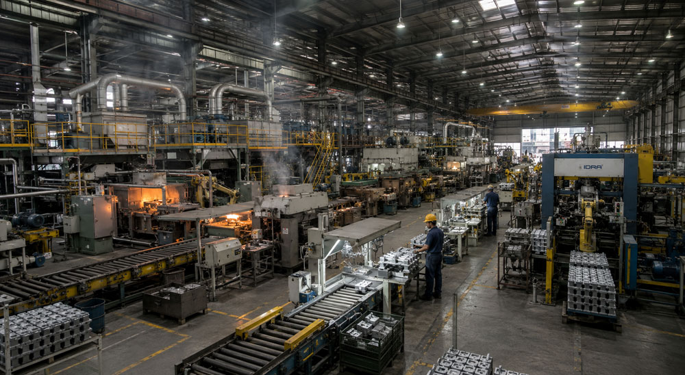
An automated line is a single dependent system. Line motors, VFD-driven drives, compressors, chillers, blowers, conveyors, PLCs, SCADA and HMI stations are electrically independent but operationally interlocked.
A component failure that would be a maintenance item on a standalone machine becomes a production event here, because everything downstream of it stops with it.
The relevant question therefore is not whether any one item survives. It is whether the electrical environment holds every layer of the line steady at the same time.
Two very different loads sharing one supply
The problem is that a process line puts two electrically incompatible load types on the same infrastructure.
| Power layer | Control layer | |
| Equipment | Line motors, VFDs, compressors, chillers, blowers | PLC, SCADA, HMI, sensors, I/O |
| Current draw | High, cyclic, non-linear | Low, steady |
| Behaviour | Repetitive peak demand, steep current rise, harmonic generation | Continuous, sensitive to input quality |
| Effect on supply | Distorts it | Depends on it |
| Failure mode | Drive faults, thermal stress | Resets, communication loss, spurious signals |
The power layer creates the conditions that the control layer is least able to tolerate, and both are fed from the same UPS.
How the cyclic power layer reaches the control layer
Process lines run to cycle. Motors start, ramp, load, brake and repeat continuously. Each of those transitions produces sharply non-linear current demand with a steep rate of rise, and each one jolts the power delivering capability of the UPS.
Under international norms, a conventional UPS is permitted to answer that jolt with a momentary distortion in the output waveform and a nominal dip in output voltage, corrected within the next power cycle. IEC and UL allow ±5% for 10ms during very high surge current events.
That permitted response is delivered to every device on the output, including the PLC, SCADA and HMI systems that have no involvement in creating the surge. The background to that allowance is set out in the industrial UPS guide.
The cascade
The failure sequence on an automated line rarely starts with the biggest load.
- A cyclic surge occurs on the power layer
- The UPS permits a momentary dip and waveform distortion
- A controller, drive or I/O module registers an unstable input
- That device faults, resets or issues a protective stop
- Interlocks propagate the stop through the sequence
- The line halts, with work in progress and a restart procedure
Nothing on the supply side is logged, so the investigation examines the device that stopped first rather than the environment that stopped it. The device is replaced. The exposure continues.
What a process automation UPS has to hold
Conventional systems hold a relatively fixed output response while the load underneath them cycles continuously. A process line is the least suitable place for that.
The ARVI HSP platform uses DVI, Dynamically Varying Impedance, continuously sensing load current and dynamically varying output impedance in real time. What it delivers is CPD, Crest Power Delivery: a clean, undistorted waveform maintained through repetitive peak demand.
For a production line that means:
- Repetitive peak demand from motors and drives handled without output voltage dip
- No crest clipping, THD held under control across cyclic operation
- No harmonic derating as the line loads up
- Control systems receiving stable power regardless of what the power layer is doing
The cumulative effect of the permitted distortion is what shortens the life of equipment power supplies across the line. Removing it protects the whole system, not just the item that failed last.
Machining centres embedded in an automated cell show the same behaviour at single-machine scale. See UPS for CNC machines.
Evaluating a UPS for a production line
- Is the UPS sized for the summed nameplate rating, or for the line actual cyclic behaviour?
- Are the control layer and power layer evaluated separately or treated as one load?
- What does the output waveform do during motor start and braking cycles?
- Is there derating as harmonic content rises with line loading?
- What is the cost of an unplanned line stoppage, and does the specification reflect it?
- Can performance be demonstrated against your load profile before dispatch?
Frequently asked questions
Usually because a controller or drive registered an unstable input and issued a protective stop, then interlocks propagated it. The instability comes from waveform distortion during cyclic peak demand rather than from loss of supply.
Separation reduces one exposure route, but it does not address the source. If the power layer UPS permits distortion, the drives it feeds are still degrading, and any shared upstream infrastructure still carries it.
Why standard industrial UPS may cost you more over time. read more
Share your line configuration and cycle profile. ARVI engineers will evaluate how your power and control layers interact electrically and where the line is exposed.