


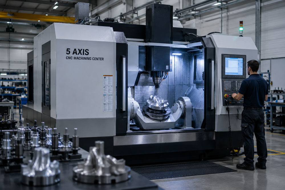
Every regenerative load has a unique regenerative profile. The magnitude of regenerative power, duration, repetition cycle, peak demand, harmonic content, and operating characteristics vary significantly from one machine/application to another. For this reason, an online UPS with regenerative load handling capability cannot be standardised.
These parameters determine how the UPS should be engineered for safe, stable, and long-term operation and protects your valuable investments.
The UPS architecture, regenerative energy handling capability, AC-side clamping configuration, converter sizing, thermal margins, protection philosophy, and control algorithms needs to be engineered around the measured regenerative load profile.
The signature symptom
Regenerative behaviour has a distinctive fingerprint:
- Cranes, hoists and lifts triggering UPS bypass during braking or lowering
- CNC and servo machines running normally, then faulting during deceleration
- DC bus overvoltage reported by drives with no corresponding supply event
- Trips that cluster around specific machine motions rather than specific times
Applications where this appears: CNC-based five-axis milling, grinding, cutting and bending machines, cranes, hoists, regenerative lifts and automated cyclic processes.
The path reverse energy takes
During braking or deceleration, the load stops consuming power and starts returning it. Power direction reverses and the energy travels back through the system:
- Out of the load
- Through the transformer
- Through the converter stages
- Through the DC link filters, inductors and capacitors
- Into the UPS DC link, raising DC bus voltage
The UPS must act at some point along that path. The two available architectures act at very different points on it.
Approach one: DBR clamping at the DC bus
Dynamic Braking Resistor is the default approach in most industrial UPS systems. Energy that reaches the DC bus is dissipated as heat once bus voltage rises past a threshold.
It works, and it has three structural limitations.
It is reactive rather than preventive. Detection happens at the DC level, which means energy is allowed to travel through the transformer, converter stages and DC link filters before anything responds.
Energy accumulates before action. Voltage rises before correction begins. By the time the DBR activates, the UPS power electronics and the connected load have already been exposed to the event.
It addresses the symptom rather than the source. DBR dissipates energy. It does not stop reverse power flow, prevent propagation through the system, or protect upstream stages from exposure.
The conversion stages and filters in that path also introduce inherent latency, which is what makes the response reactive by design rather than by tuning.
Approach two: real-time AC-side clamping at source
The alternative shifts control from the DC bus to the point where the energy originates.
- Regenerative power is detected at the load side
- Reverse power flow is identified instantaneously
- Clamping is triggered in real time
- Energy is controlled before it enters the UPS DC link
Nothing travels through the conversion stages, so nothing accumulates.
Side by side
| DBR, DC-side clamping | Real-time AC-side clamping | |
| Point of control | UPS DC bus | Load side, at source |
| Timing | After energy arrives | On detection of reverse flow |
| Latency source | Transformer, converter stages, DC link filters | None from conversion path |
| Energy build-up before action | Yes | No |
| DC bus voltage rise | Occurs, then corrected | Prevented |
| Exposure of power electronics | Repeated | Avoided |
| Method | Dissipation as heat | Prevention of entry |
| Character | Reactive | Preventive |
This is an architecture difference, not a feature difference
Two systems can carry the same kVA rating, the same topology description and the same compliance certifications while differing entirely on this point, because it is not a line item on a datasheet.
In regenerative environments the difference determines whether the system absorbs stress repeatedly or prevents it. The consequence is not immediate failure. It is cumulative degradation: repeated exposure to voltage rise, harmonic distortion and crest clipping producing premature component failure, increased maintenance cycles and reduced machine life.
Which is the same underlying pattern described across industrial environments in the industrial UPS guide, where failures are driven by power quality under stress rather than power availability.
What load-specific engineering requires here
Handling regenerative loads properly cannot be done from a nameplate rating. It requires:
- Evaluation of peak regenerative power
- Measurement of the duration and frequency of regeneration cycles
- Analysis of load behaviour under real operating conditions
Only then can the system be engineered to control reverse energy flow, prevent propagation into sensitive stages and maintain stability across cyclic regeneration.
Servo-driven machining centres show the same behaviour during rapid deceleration. See UPS for CNC machines.
Frequently asked questions
A load that returns energy to the supply rather than only consuming it. It occurs whenever a motor is driven by its own inertia or by gravity, such as during braking, deceleration, or lowering a suspended load.
Because that is when power direction reverses. Energy flows back toward the UPS and raises DC bus voltage. If the system has no means of controlling that before it arrives, protection responds by tripping or transferring to bypass.
Share your application, cycle frequency and machine motions. ARVI engineers will evaluate peak regenerative power and recommend the appropriate control architecture.